WhatsApp:+86 15989059026 E-mail:info@xierli.com
Abstract: Manufacturers of SPDs understand that their devices will
eventually reach an end-of-life state, whether due to natural aging or due to
conditions being imposed which are outside of normal operating conditions.
International standards bodies such as the Electro Technical Commission (IEC) and Underwriters Laboratories Incorporated (UL) recognized the hazard posed by a failed SPD and include a number of tests in standards such as IEC 61643-12, IEC 62305-4 and UL 1449, to ensure that such devices fail in a safe manner. In order to comply with such standards, SPD manufacturers rely on “disconnectors”. This paper introduces the importance of SPD “disconnectors” to the safe installation of an SPD and expands on aspects such as,internal versus external disconnectors and over-current versus thermal disconnectors. It also details the current methods used to evaluate the behaviour of disconnectors by these various standards setting bodies and the steps being taken to improve on these in new draft editions under development.
An SPD by
definition contains at least one nonlinear component which is intended to limit
the surge voltage and divert the surge current. Inherent in the operation of
such devices is the possibility of unexpected failure or rapid end
of-life. Under such conditions, it is important that the SPD can safely isolate
itself from the prospective supply to which it is connected without presenting
a potential fire hazard.For this purpose a disconnector is usually
incorporated,either in the housing of the SPD itself (internal disconnector),
or as a separate component installed in the electrical network up-stream of the
SPD (external disconnector).
The
importance of such disconnectors to the safe operation of an SPD can not
be over emphasized. It is for this reason that manufacturers put so much
engineering effort into the careful design of disconnectors and standards
committees,such as UL 1449 and IEC 61643-1 , into the testing and
evaluation of such devices.
A well
designed SPD, or SPD installation, will generally require one or more
disconnectors for safe isolation from the prospective current of the energizing
supply during fault conditions. Without such, it is a potential fire hazard or
explosion waiting to happen.
The
failure mechanism of an SPD can generally be categorised as:
§ A gradual end-of-life due to natural degradation (ageing) of the internal non-linear component(s) during normal operation, or
§ A rapid
end-of-life due to a catastrophic event outside the scope of the SPD’s normal
range of operation.
These two
scenarios, by which an SPD can reach its end-of life,undefined
undefined
undefined
undefined,undefined
undefined undefined
undefined,undefined
undefined. undefined
undefined
undefined
undefined
undefined,undefined
undefined:
undefinedundefined
undefined
undefinedundefined
undefinedundefined,undefined
undefined undefined,undefined
undefined
undefined
undefined undefined,undefined undefined undefined,undefined
undefined undefined undefined undefined undefined,undefined undefined undefined undefined undefined. undefined,undefined undefined undefined,undefined undefined
undefined,undefined undefined undefined,undefined. undefined undefined,undefined undefined undefined
undefined undefined undefined undefined undefined undefined undefined undefined. undefined,undefined undefined undefined undefined undefined. undefined undefined,undefined,undefined, but it also has to disconnect (open) when there is no zero crossing point to extinguish an arc as there would be on an AC system.
SPD
manufacturers are only just starting to address these more onerous
requirements. A number of innovative new disconnection designs have been developed
and patented.
Most of
these use various mechanical shutters to extend the arc length while
disconnecting, thereby cause self extinguishing even though a voltage
zero-crossing point is not present.
Surge Protection for Energy Storage Systems(ESS)
Energy Storage Systems (ESS) are now a mature technology. ESS is installed at sites to improve energy management control such as peak management or frequency regulation, or for renewable energy storage for photovoltaic or wind generated energy applications. The importance of such equipment makes interruption of their service unacceptable, so measures must be taken to limit damage due to external influences. One of the risks to be taken into account is possible damage due to transient overvoltages generated by lightning or by switching operations.
The deployment of ESS has demonstrated the limited robustness of these equipments, including batteries systems. Specialists in this technology have ascertained that their low impulse voltage withstand (Uw) may lead to critical system failure.
Surge Protector for ESS
Surge Protection Device (SPD) technology is widely used in AC power networks to protect equipment connected to them against transient overvoltages. Test standards (IEC61643-11), and selection and installation guides (IEC61643-12, IEC60364-5-534) have been in existance for many years, they define reliable products as well as their selection and implementation. However, regarding DC power networks, neither standardization is available at the time of writing (late 2020). In fact, the standards for surge protection for DC power are ongoing at international level (IEC) such as the following standards:
This standard IEC61643-31 is extrapolated from existing standards of surge protection devices for AC networks (IEC61643-11) and the sizing parameters (In, Uc, Imax, Up…) and test procedures is similar because they will be grouped in a new document common to the two documents.
The IEC 61643 series is moving toward a new philosophy. A new document (IEC61643-01) will gather all the definitions and tests common to the various applications of SPDs (AC power, PV power, Dataline, DC power) and the dedicated standards ( IEC61643-11, IEC6163-21, IEC61643-31, and coming IEC61643-41) will focus only on the specific tests for the application.
Regarding safety tests that simulate the end of life of the SPD such as thermal runaway or short circuit behavior, the procedures are therefore similar as well as the necessary means to achieve requirements, namely the use of internal disconnectors to withstand the thermal runaway tests, and associated fuses to withstand short-circuit tests.
The need to protect ESS equipement against transient over-voltages
Specialists in ESS equipment have noted a reduced robustness in impulse overvoltage of these equipments – particularly in battery systems – and due to the imperative need for continuity of service they recommend the use of surge protectors at their terminals. Surge protection on the AC part is also recommended. For the following reasons and consequences, the critical point is the protection of the battery storage system. When the maximum DC operating voltage is very high (1000 Vdc and more), in such cases a specific SPD is necessary, it being compatible with these voltages and in conformity with the future IEC61643-41. In cases of potentially extremely high short circuit current (100kA and more), the surge protector must withstand the short-circuit test being associated with a fuse sized accordingly.
To manage the short-circuit test, it is imperative that the surge protector is used with an external fuse. The fuse must be rated high enough to conduct 5kA at 8/20μs impulse current without opening, but rated low enough to protect the surge protector during its failure on the short-circuit test. Regarding the breaking capacity, this is the likely short circuit current calculated at the time of installation. Provided by the surge protection manufacturer, these requirements can make fuse rating selection somewhat difficult in the case of very high power DC installations.
Use of the existing upstream fuse
It could be considered to use the existing AC power SPD overload protection fuse upstream as protection of the SPD. This is only possible if its rating is equal to or less than the value declared by the manufacturer of the SPD. For high power installations, the fuses have very high ratings, making this option a non-starter.
ESS surge protector selection
In conclusion, the key criteria for the selection of DC SPDs, extrapolated from AC standards is:
* Type 2 Surge Protector (no proven risk of direct lightning discharge)
* Uc (max. operating voltage) is greater than Umax of the DC network + 10%
* In (Nominal discharge current) is greater than 5kA
* Isccr (admissible short-circuit current) with associated fuse is greater than Icc at the installation point.
(source: pewholesaler.co.uk by Switchtec Ltd)
To mitigate the effects of transient overvoltages, Surge Protective Devices (SPDs) are used throughout electrical distribution systems, such as at service entrances, transfer switches, and downstream panelboards. Manufacturers state surge capacity ratings as either Per Mode or Per Phase. This paper describes how these terms apply to SPDs used in three-phase, four-wire Wye systems.
SPD Modes Defined
In the context of SPDs, the term mode refers to the types of pathways available for shunting overvoltages. These pathways are most commonly formed by bridging two conductors through a Metal Oxide Varistor (MOV). These components are non-conductive at nominal circuit voltages, but become conductive when higher voltages are present. When that occurs, the varistor shunts excess voltage from the conductor of higher potential to the conductor of lower potential.
In a three-phase four-wire systems, four pathways are possible:
• Line-to-Neutral
• Line-to-Ground
• Neutral-to-Ground
• Line-to-Line
Each is shown in Figure 1.
Many three-phase applications use SPDs that offer complete line-to-neutral, line-to-ground, and neutral-to ground pathways, for a total of seven modes of protection. This arrangement is shown in Figure 2. SPDs that also provide line-to-line pathways offer 10 modes of protection. This brief will use seven-mode SPDs in subsequent examples.
Per Mode Rating Defined
An SPD’s per mode rating is based on the total amount of energy it can shunt from one circuit conductor to another. If an MOV capable of shunting a 50 kA of current is used in each pathway, then the per mode rating of the SPD in Figure 3 is 50kA.
If multiple MOVs are used between the same conductors, then the per mode rating will be the sum of the capacity of the MOV’s used in these pathways. Figure 4 shows a seven-mode SPD with three 50 kA MOVs installed between each pair of conductors. The per mode rating of this MOV is 150kA.
Per Phase Rating Defined
A different way to rate an SPD is to state the total capacity of the protective components serving each of the three phase conductors. Using the same seven-mode SPD with 50 kA MOVs, Phases A, B, and C are each served by two MOVs (one to neutral, one to ground). The per phase rating for the same SPD is 100 kA, as shown in Figure 5 below. Applying the same rating scheme to the SPD in Figure 4 above produces a per phase rating of 300 kA because each phase conductor is served by six 50 kA MOVs.
1.1:La tecnología del pararrayos REPSUN:
La última tecnología basada en la emisión temprana de streamers.
1.2:La tecnología del pararrayos convencional.:
Diseño de alrededor de 260 años basado en tecnología Franklin.
2.1:Principio de funcionamiento del pararrayos REPSUN.
A. El dispositivo de ionización se carga a través de los electrodos inferiores utilizando el campo eléctrico ambiental (varios millones de voltios/metro cuando prevalecen las tormentas).. Esto significa que el sistema de pararrayos REPSUN ESE es un sistema totalmente autónomo que no requiere fuente de alimentación externa.
B. El fenómeno de ionización está controlado por un dispositivo que detecta la aparición de un líder descendente,El campo eléctrico local aumenta rápidamente cuando una descarga es inminente.. Pararrayos REPSUN ESE detecta cargas en el campo,convirtiéndola en la primera terminal aérea de ESE en reaccionar en el momento preciso en que el líder descendente se desarrolla desde la nube hasta el suelo.
C. Activación temprana del líder ascendente mediante un sistema de ionización por chispa entre los electrodos superiores y la punta central.. La capacidad del pararrayos REPSUN ESE es activar un líder ascendente por delante de cualquier otro punto que sobresalga en el área protegida, lo que garantiza que será el punto de impacto preferencial para la descarga del rayo.
2.2 Principio de trabajo de la varilla convencional.
Depende de la corona que ocurre naturalmente y, por lo tanto, de la enorme corriente que fluye a través de las varillas y los conductores de bajada, lo que resulta en destellos internos y aumento del potencial de tierra (es decir,. la varilla siempre esperará a que un rayo caiga sobre la punta de la varilla). En caso de que las fábricas produzcan naturalmente cargas como productos químicos y metales que puedan atraer la corriente del rayo en sus partes metálicas.. En este momento,la parte metálica que emite cargas se vuelve más activa que el pararrayos que está inactivo&erio;La corriente del rayo golpeará la parte metálica en lugar de golpear el pararrayos.
3.1 Radio de protección del pararrayos REPSUN ESE VS pararrayos convencional
Pararrayos REPSUN ESE:Radio de protección más amplio según el estándar NFC17-102:2011
3.2 Pararrayos convencional:Limitar el radio de protección
REPSUN ofrece nombre de usuario y contraseñas para iniciar sesión en el sitio web de monitoreo inteligente en línea de REPSUN como se muestra a continuación:
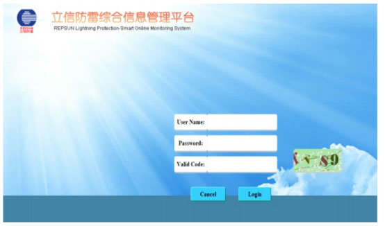
El código válido debe estar todo en minúsculas.
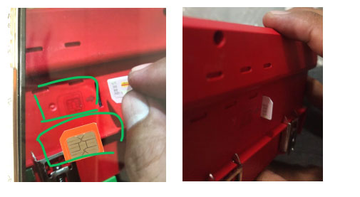
1.Cómo insertar la tarjeta SIM en el host Smart GSM?
En primer lugar,Podemos ver el diagrama al lado del puerto de la tarjeta SIM.,según el mensaje del diagrama:poner la dirección correcta de la tarjeta,y luego insertar.
2.Cómo sacar la tarjeta SIM del host GSM inteligente?
Primero,Necesitamos encontrar cosas un poco puntiagudas (por ejemplo,aguja/punta de retorno,etc.),y luego úselo para presionar la tarjeta SIM,y aparecerá automáticamente.
3.Cómo conectar la resistencia al host GSM inteligente para probar el valor de resistencia?
Encuentre resistencias adecuadas antes de realizar la prueba.,Tenga en cuenta que el rango de valores de resistencia de nuestro producto es (0,01-500 Ω). Asegúrese también de que los extremos PC y E estén bien conectados.
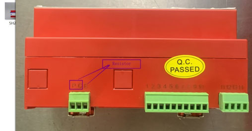
El motivo por el que necesitamos probarlo con una resistencia está diseñado para verificar la precisión de nuestros productos.
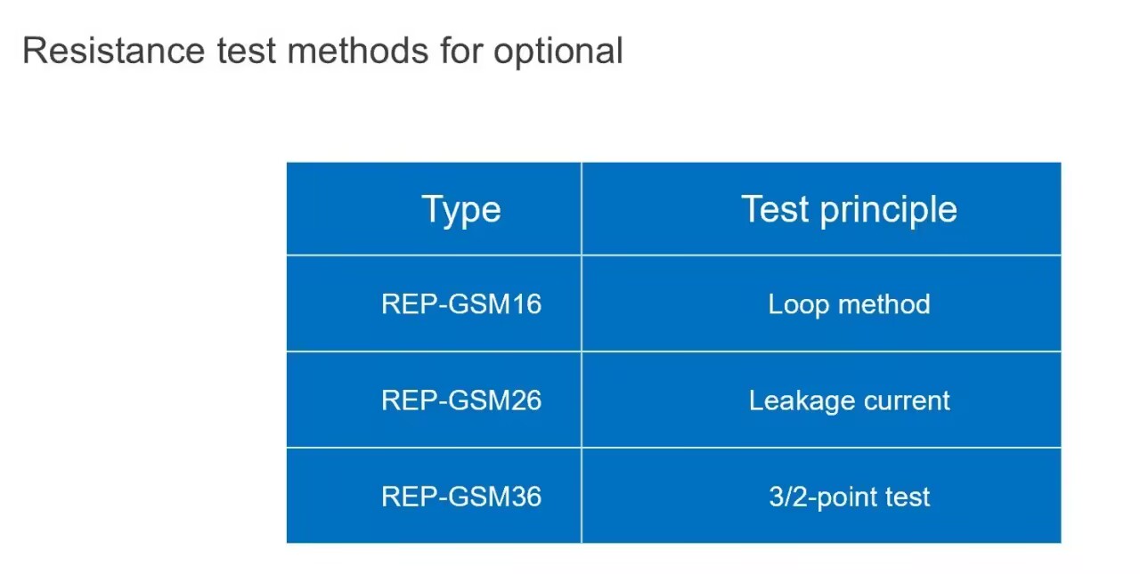
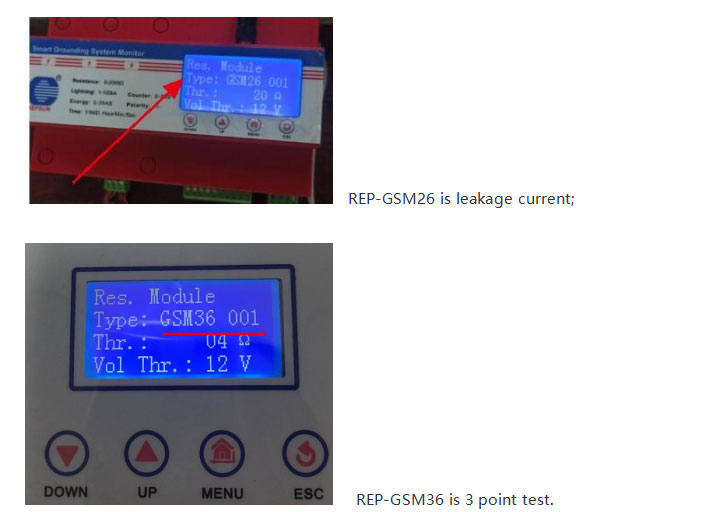
4.¿Cuántos modelos de Smart GSM tienen??
Tres tipos:
REP-GSM16 es el método de bucle;
REP-GSM26 es corriente de fuga;
REP-GSM36 es una prueba de 3 puntos.
5.Cómo modificar el modelo en el host GSM inteligente para"GSM36 001"?
①.Por favor, cámbielo a"Tipo:GSM36 001"luego presione el botón MENÚ y el botón ARRIBA para cambiarlo
②.Entonces 001,También es necesario presionar el botón MENÚ para guardarlo.
③."tr"También es necesario presionar el botón MENÚ.
④."Vol. Thr"También es necesario presionar el botón MENÚ.
⑤.Finalmente presione el"ESC"botón si termina el paso anterior,Necesita reiniciar el Smart GSM y luego verificar nuevamente el"Tipo:GSM36 001"está bien.
6.Cómo probar el valor de resistencia del Smart GSM?
Pruebas GSM inteligentes:Antes de realizar la prueba GSM inteligente, es necesario asegurarse de que el estado del monitor de resistencia a tierra esté activado.
Podemos seguir este paso para comprobarlo.:
①.Presione 1 vez el botón MENÚ,y busque el mensaje "Sys. Set.(Configuración del sistema)” y luego presione nuevamente el botón MENÚ.
②.Cuando ingresas al menú “Sys. Establecer.(Configuración del sistema)”,necesitas encontrar el"Res.Module (módulo de resistencia a tierra)"presione nuevamente el botón MENÚ.
③.Cuando ingresas al"Res.Module (módulo de resistencia a tierra)",necesitas encontrar"Res.Monitor (Monitor de resistencia a tierra)"
④.Compruebe el"Res.Monitor (Monitor de resistencia a tierra)"Está encendido.
Asegúrate que"Res.Monitor (Monitor de resistencia a tierra)"Está encendido,Entonces podremos empezar a probar el Smart GSM.
CAMINO 1:Sitio web para hacer clic en"Prueba"Luego esperando que lleguen los datos.
CAMINO 2:También puede presionar 4 veces el botón ABAJO,luego 1 vez para el botón MENÚ. (Requiere una presión continua y constante).
7.Cómo modificar la información de la versión de la página web?
Necesidad de modificar: FMMon. (Monitoreo de señal remota)
①.Presione el"MENÚ"botón encontrar el Sys. Set.(Configuración del sistema) luego presione nuevamente el"MENÚ"botón entrar en nueva página.
②.Encuentra el"FMMon.(Monitoreo de señal remota) luego presione el"MENÚ"botón entrar en nueva página.
③.Presione nuevamente el"MENÚ"botón y presione"ARRIBA"botón para cambiar el"EN"a"APAGADO"
④.Presione el"MENÚ"para guardar la configuración.
Un SPD que proporciona monitoreo de su entorno y capacidad de comunicación (ya sea local o remota) para proporcionar el estado del SPD, así como la esperanza de vida y posiblemente otras funciones, como la intensidad de las sobretensiones.,contador de sobretensiones,tiempo de sobretensión,corriente de fuga,resistencia a tierra,conectividad del cable de tierra,temperatura y humedad,etc.
Inteligente implica dos cosas:Interacción con otros dispositivos basada en comunicación lejana (internet de las cosas), y cuando sea posible una cinta de análisis (para informar a un usuario que el SPD ha fallado en Niza,pero por qué ha fallado es más inteligente).
Los SPD inteligentes suelen incluir tres funciones:Protección contra sobretensiones,seguimiento y comunicación.
Función de monitoreo del estado de operación del SPD&erio;parámetros de detección;Puede coincidir con la interfaz de comunicación.&erio;transmisión remota de datos.
Debido al hecho de que la mayoría de nuestros SPD tienen carcasas y piezas de plástico,en caso de cortocircuito o sobrecarga del SPD,se disipará una gran cantidad de calor,la carcasa de plástico o las piezas podrían deformarse,Esto podría impedir que el mecanismo de liberación funcione según el diseño original del SPD.,y no se desconecta de la alimentación principal. Por tanto, por doble motivo de seguridad.,Además, en el SPD de potencia aguas arriba también instalamos un fusible o disyuntor.
Pero REPSUN SPD no requiere fusible o CB ya que ya hay un fusible de respaldo en REPSUN SPD para doble seguridad.