При проектировании и установке систем распределения электроэнергии инженеры и подрядчики должны выбирать устройства защиты от перенапряжения (УЗИП) для защиты электрооборудования и систем от переходных перенапряжений. Для этого специалисты по спецификациям должны понимать различия между параллельно и последовательно соединенными УЗИП и где лучше всего применять каждый тип устройства. Ниже приводится краткое описание конструкции и функций параллельно и последовательно соединенных УЗИП, а также описываются некоторые распространенные применения для каждого из них.
ОБЗОР
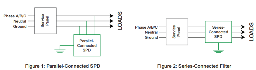
Правильное применение включает знание типа устанавливаемого устройства и способа подключения УЗИП к системе распределения электроэнергии. Как правило, параллельно подключенное устройство устанавливается на электрическом распределительном щите или щитке, как правило, на выделенном сервисном разъединителе, таком как автоматический выключатель. В качестве альтернативы, автономные последовательно подключенные фильтры подключаются в линию вблизи защищаемого оборудования нагрузки. На рисунках 1 и 2 показан каждый тип.
ПАРАЛЛЕЛЬНО СОЕДИНЕННЫЕ УСТРОЙСТВА
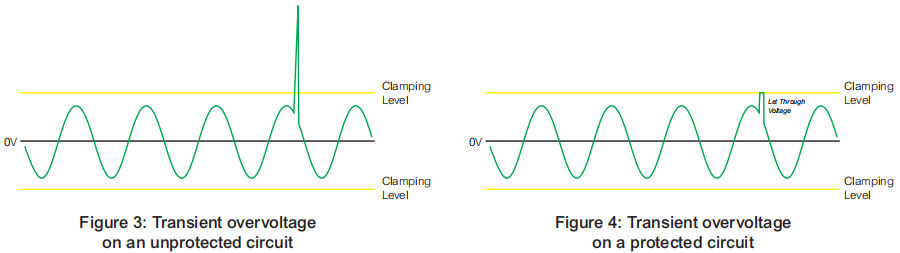
В параллельно соединенных ОПН чаще всего используются металлооксидные варисторы (MOV) для отвода переходных перенапряжений от нагрузок. Эти чувствительные к напряжению компоненты проводят ток только тогда, когда перенапряжение превышает уровень фиксации варистора. Как показано на рисунках 3 и 4, эти ОПН начинают шунтировать избыточное напряжение, когда напряжение превышает уровень фиксации. Остаточное напряжение, находящееся ниже уровней фиксации, но выше синусоиды, известно как пропускаемое напряжение.
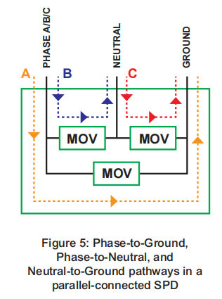
В параллельно соединенных ОПН варисторы MOV подключаются к каждому режиму электрической системы. Длина результирующих путей перенапряжения зависит от длины проводников, установленных для подключения устройства к его цепи. Длина выводов напрямую влияет на производительность устройства, причем большая длина выводов соответствует большему пропускаемому напряжению. Следовательно, параллельно соединенные ОПН следует устанавливать как можно ближе к защищаемым ими щиткам. На рисунке 5 показаны пути перенапряжения через параллельно соединенное устройство.
Параллельно соединенные УЗИП способны фиксировать высокоэнергетические низкочастотные переходные процессы. Их преимущества включают более низкую стоимость и меньшие размеры, чем у последовательно соединенных устройств, а также процедуры установки, не требующие прерывания питания нагрузок. Их недостатки включают различия в производительности в зависимости от длины установленных выводов, мгновенные пропускаемые напряжения, которые изменяются в зависимости от фазового угла, и отсутствие ослабления высокочастотного шума.
ПОСЛЕДОВАТЕЛЬНО СОЕДИНЕННЫЕ УСТРОЙСТВА
Series-connected devices fall into two broad categories – series-connected SPDs and series-connected filters. Typically, series-connected SPD designs are wired in series, but internal suppression components are connected in parallel to the circuit. The benefit of this configuration is that lead length is not added during installation, allowing the device to clamp impulses at tighter levels than a parallel-connect unit. The ampere ratings of series-connected units are limited by their lug or terminal block characteristics.
Series-connected filters are designed to protect sensitive equipment, such as computers and digitally controlled equipment, from high-frequency noise that could disrupt reliable operation. Manufacturers offer these products to provide protection from high-frequency, low-energy transient overvoltages as well as noise filtering. As shown in Figure 6, these devices mitigate voltage whenever transient voltages exceed the instantaneous nominal voltage by a specified amount, regardless of phase angle.
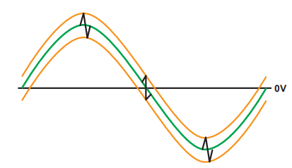
Figure 6: tightly controls let-through voltage, regardless of phase angle
Series-connected filters use a low-pass circuit (consisting of series-connected inductors, capacitors, and resistors) to eliminate high-frequency noise. Because the entire load current passes through the components, the device must be designed to pass all of the current carried by the circuit it serves. As a result, series-connected filters are typically larger and more costly than parallel-connected devices.
Series-connected filters employ many different technologies. Figure 7 below shows a typical hybrid design with MOVs acting as a first line of defense, clamping the initial overvoltage event. The inductors and capacitors then mitigate the remaining let through voltage, providing a filtered sign wave to the connected equipment.
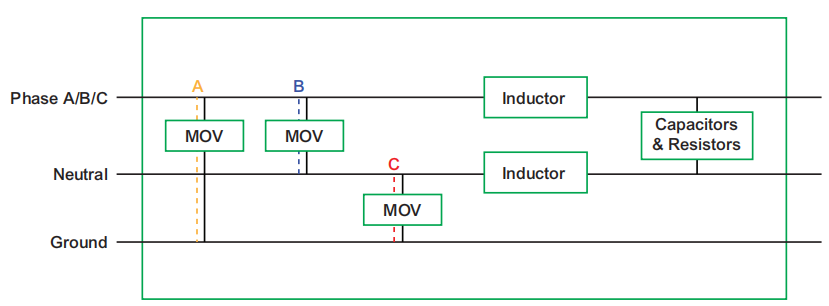
Figure 7: Phase-to-Ground, Phase-to-Neutral, and Neutral-to-Ground pathways in a series-connected filter
Benefits of series-connected devices include mitigation of potentially damaging high-frequency noise, a tighter clamping voltage, and performance that is independent of installation practices.
DEVICE SELECTION
During the design process, specifiers must decide where to use parallel-connected SPDs and where to use series-connected filters. The appropriate selection could depend on whether protection is needed against damage to equipment, disruption of operations, or both. It also depends on the location in the power distribution where the device will be installed.
Differing types of transients are likely to occur at different locations within a power distribution system. Studies show that 20-30 percent of transient overvoltages originate externally, from environmental and utility sources, and are more likely to consist of high-energy, low-frequency impulses. That means 70-80 percent originate from equipment and operations inside of a facility, and are more likely to consist of low-energy, high-frequency noise, such as ring waves. If destructive high-energy transients pose the greatest risks, then a parallel-connected device is likely to be the most cost effective solution. Consequently, parallel-connected devices are most often used at or near a building’s service entrance and on panels and equipment that manage large amounts of load. If sensitive equipment could be disrupted by high�frequency noise, then a series-connected filter may be the best choice. Where multiple types of transients may occur or where the characteristics of any power disturbance are unknown, then a staged strategy involving both parallel-connected and series-connected devices should be used. Effective protection is often provided when parallel-connected SPDs are installed at service entrances and distribution panels, and series-connected devices are installed near load equipment.
SUMMARY
Parallel-connected SPDs typically use voltage-sensitive MOVs that conduct current only when line voltage exceeds their maximum continuous operating voltage. Parallel-connected SPDs are capable of clamping high-energy, low-frequency transients.
Series-connected filters provide protection from low-energy transient overvoltages as well as noise filtering. These devices provide consistent clamping of let-through voltages regardless of phase angle, and are usually installed close to critical loads.
Cascading parallel-connected devices at service entrances and power distribution panels, coupled with series-connected devices at both load equipment and internal sources of transients and noise, can provide comprehensive protection from a range of potentially damaging and disruptive surge events.
 Русский
 English
 Español
 العربية
 Français