WhatsApp:+86 15989059026 E-mail:info@xierli.com
Abstract: Manufacturers of SPDs understand that their devices will
eventually reach an end-of-life state, whether due to natural aging or due to
conditions being imposed which are outside of normal operating conditions.
International standards bodies such as the Electro Technical Commission (IEC) and Underwriters Laboratories Incorporated (UL) recognized the hazard posed by a failed SPD and include a number of tests in standards such as IEC 61643-12, IEC 62305-4 and UL 1449, to ensure that such devices fail in a safe manner. In order to comply with such standards, SPD manufacturers rely on “disconnectors”. This paper introduces the importance of SPD “disconnectors” to the safe installation of an SPD and expands on aspects such as,internal versus external disconnectors and over-current versus thermal disconnectors. It also details the current methods used to evaluate the behaviour of disconnectors by these various standards setting bodies and the steps being taken to improve on these in new draft editions under development.
An SPD by
definition contains at least one nonlinear component which is intended to limit
the surge voltage and divert the surge current. Inherent in the operation of
such devices is the possibility of unexpected failure or rapid end
of-life. Under such conditions, it is important that the SPD can safely isolate
itself from the prospective supply to which it is connected without presenting
a potential fire hazard.For this purpose a disconnector is usually
incorporated,either in the housing of the SPD itself (internal disconnector),
or as a separate component installed in the electrical network up-stream of the
SPD (external disconnector).
The
importance of such disconnectors to the safe operation of an SPD can not
be over emphasized. It is for this reason that manufacturers put so much
engineering effort into the careful design of disconnectors and standards
committees,such as UL 1449 and IEC 61643-1 , into the testing and
evaluation of such devices.
A well
designed SPD, or SPD installation, will generally require one or more
disconnectors for safe isolation from the prospective current of the energizing
supply during fault conditions. Without such, it is a potential fire hazard or
explosion waiting to happen.
The
failure mechanism of an SPD can generally be categorised as:
§ A gradual end-of-life due to natural degradation (ageing) of the internal non-linear component(s) during normal operation, or
§ A rapid
end-of-life due to a catastrophic event outside the scope of the SPD’s normal
range of operation.
These two
scenarios, by which an SPD can reach its end-of life, generally place very
different requirements on the disconnector(s).
Thermal
disconnector - In the first case, where the failure is associated with a
gradual degradation of the internal non linear components (metal oxide
varistors), a disconnector which is capable of sensing the thermal rise in
temperature of the SPD is generally required. The objective being to isolate
the failing varistor before it reaches thermal runaway and becomes a fire
hazard.
Gradual
degradation of the SPD can result from many causes, but most common amongst
these are:
§ Ageing
of the metal oxide varistor (MOV).
§ Sustained
temporary overvoltages (TOV) of the power system, either due to poor system
regulation (as in the case of long transmission lines), or when a
multiphase system becomes unbalanced (as in the case of a loose neutral
connection on US 120/240V systems).
Under such conditions, the rms current conducted by the SPD is usually limited to a few tens of amperes as it starts to enter conduction on the peaks of the sinusoidal supply, resulting in a progressive and gradual rise in temperature.
Over-current disconnector - In the case of the very rapid end-of-life (which can occur when an SPD is exposed to unanticipated events such as - a surge beyond its intended rating, or a large TOV as can occur when there is comingling of the HV and LV system) the disconnector must operate extremely fast in order to limit the energy of the prospective short-circuit current available from the supply to which it is connected. Under such conditions, a thermal disconnector would operate too slowly and the energy created in the failed SPD could result in a catastrophic explosion of the housing, and fire due to mains follow-current.
To prevent this, an “over-current disconnector” such as a fast acting fuse or magnetic circuit breaker with well coordinated I2t characteristic, is required. This need to include fast operating over-current disconnectors, has also meant that manufacturers need to grapple with a trade-off between fast isolation (high SCCR rating) and a low Imax (low maximum discharge current).
DC current disconnector – The growing interest in renewable energy generation has lead to a proliferation of photovoltaic panels in applications ranging from small residential installations to large commercial “sun farms”.Such installations by their very nature are externally located and thus particularly subject to the effects of lightning induced damage. As a result, the use of SPDs on such panels is becoming increasing important and new standards are being developed to address the testing and performance of SPDs intended for use on DC power systems. The disconnector in a DC-SPD needs to be designed in a very different way to that used in an AC-SPD. Not only does it often have to isolate much higher voltages (photovoltaic systems typically operate at 300, 600, 1000 VDC), but it also has to disconnect (open) when there is no zero crossing point to extinguish an arc as there would be on an AC system.
SPD
manufacturers are only just starting to address these more onerous
requirements. A number of innovative new disconnection designs have been developed
and patented.
Most of
these use various mechanical shutters to extend the arc length while
disconnecting, thereby cause self extinguishing even though a voltage
zero-crossing point is not present.
Surge Protection for Energy Storage Systems(ESS)
Energy Storage Systems (ESS) are now a mature technology. ESS is installed at sites to improve energy management control such as peak management or frequency regulation, or for renewable energy storage for photovoltaic or wind generated energy applications. The importance of such equipment makes interruption of their service unacceptable, so measures must be taken to limit damage due to external influences. One of the risks to be taken into account is possible damage due to transient overvoltages generated by lightning or by switching operations.
The deployment of ESS has demonstrated the limited robustness of these equipments, including batteries systems. Specialists in this technology have ascertained that their low impulse voltage withstand (Uw) may lead to critical system failure.
Surge Protector for ESS
Surge Protection Device (SPD) technology is widely used in AC power networks to protect equipment connected to them against transient overvoltages. Test standards (IEC61643-11), and selection and installation guides (IEC61643-12, IEC60364-5-534) have been in existance for many years, they define reliable products as well as their selection and implementation. However, regarding DC power networks, neither standardization is available at the time of writing (late 2020). In fact, the standards for surge protection for DC power are ongoing at international level (IEC) such as the following standards:
This standard IEC61643-31 is extrapolated from existing standards of surge protection devices for AC networks (IEC61643-11) and the sizing parameters (In, Uc, Imax, Up…) and test procedures is similar because they will be grouped in a new document common to the two documents.
The IEC 61643 series is moving toward a new philosophy. A new document (IEC61643-01) will gather all the definitions and tests common to the various applications of SPDs (AC power, PV power, Dataline, DC power) and the dedicated standards ( IEC61643-11, IEC6163-21, IEC61643-31, and coming IEC61643-41) will focus only on the specific tests for the application.
Regarding safety tests that simulate the end of life of the SPD such as thermal runaway or short circuit behavior, the procedures are therefore similar as well as the necessary means to achieve requirements, namely the use of internal disconnectors to withstand the thermal runaway tests, and associated fuses to withstand short-circuit tests.
The need to protect ESS equipement against transient over-voltages
Specialists in ESS equipment have noted a reduced robustness in impulse overvoltage of these equipments – particularly in battery systems – and due to the imperative need for continuity of service they recommend the use of surge protectors at their terminals. Surge protection on the AC part is also recommended. For the following reasons and consequences, the critical point is the protection of the battery storage system. When the maximum DC operating voltage is very high (1000 Vdc and more), in such cases a specific SPD is necessary, it being compatible with these voltages and in conformity with the future IEC61643-41. In cases of potentially extremely high short circuit current (100kA and more), the surge protector must withstand the short-circuit test being associated with a fuse sized accordingly.
To manage the short-circuit test, it is imperative that the surge protector is used with an external fuse. The fuse must be rated high enough to conduct 5kA at 8/20μs impulse current without opening, but rated low enough to protect the surge protector during its failure on the short-circuit test. Regarding the breaking capacity, this is the likely short circuit current calculated at the time of installation. Provided by the surge protection manufacturer, these requirements can make fuse rating selection somewhat difficult in the case of very high power DC installations.
Use of the existing upstream fuse
It could be considered to use the existing AC power SPD overload protection fuse upstream as protection of the SPD. This is only possible if its rating is equal to or less than the value declared by the manufacturer of the SPD. For high power installations, the fuses have very high ratings, making this option a non-starter.
ESS surge protector selection
In conclusion, the key criteria for the selection of DC SPDs, extrapolated from AC standards is:
* Type 2 Surge Protector (no proven risk of direct lightning discharge)
* Uc (max. operating voltage) is greater than Umax of the DC network + 10%
* In (Nominal discharge current) is greater than 5kA
* Isccr (admissible short-circuit current) with associated fuse is greater than Icc at the installation point.
(source: pewholesaler.co.uk by Switchtec Ltd)
To mitigate the effects of transient overvoltages, Surge Protective Devices (SPDs) are used throughout electrical distribution systems, such as at service entrances, transfer switches, and downstream panelboards. Manufacturers state surge capacity ratings as either Per Mode or Per Phase. This paper describes how these terms apply to SPDs used in three-phase, four-wire Wye systems.
SPD Modes Defined
In the context of SPDs, the term mode refers to the types of pathways available for shunting overvoltages. These pathways are most commonly formed by bridging two conductors through a Metal Oxide Varistor (MOV). These components are non-conductive at nominal circuit voltages, but become conductive when higher voltages are present. When that occurs, the varistor shunts excess voltage from the conductor of higher potential to the conductor of lower potential.
In a three-phase four-wire systems, four pathways are possible:
• Line-to-Neutral
• Line-to-Ground
• Neutral-to-Ground
• Line-to-Line
Each is shown in Figure 1.
Many three-phase applications use SPDs that offer complete line-to-neutral, line-to-ground, and neutral-to ground pathways, for a total of seven modes of protection. This arrangement is shown in Figure 2. SPDs that also provide line-to-line pathways offer 10 modes of protection. This brief will use seven-mode SPDs in subsequent examples.
Per Mode Rating Defined
An SPD’s per mode rating is based on the total amount of energy it can shunt from one circuit conductor to another. If an MOV capable of shunting a 50 kA of current is used in each pathway, then the per mode rating of the SPD in Figure 3 is 50kA.
If multiple MOVs are used between the same conductors, then the per mode rating will be the sum of the capacity of the MOV’s used in these pathways. Figure 4 shows a seven-mode SPD with three 50 kA MOVs installed between each pair of conductors. The per mode rating of this MOV is 150kA.
Per Phase Rating Defined
A different way to rate an SPD is to state the total capacity of the protective components serving each of the three phase conductors. Using the same seven-mode SPD with 50 kA MOVs, Phases A, B, and C are each served by two MOVs (one to neutral, one to ground). The per phase rating for the same SPD is 100 kA, as shown in Figure 5 below. Applying the same rating scheme to the SPD in Figure 4 above produces a per phase rating of 300 kA because each phase conductor is served by six 50 kA MOVs.
1.1:Технология громоотвода REPSUN:
Новейшая технология, основанная на раннем излучении стримера.
1.2:Технология обычного громоотвода:
Дизайн, которому около 260 лет, основан на технологии Франклина.
2.1:Принцип работы молниеотвода REPSUN
А. Ионизирующее устройство заряжается через нижние электроды с использованием окружающего электрического поля (несколько миллионов вольт/метр, когда преобладают грозы).. Это означает, что система молниеотвода REPSUN ESE является полностью автономной системой, не требующей внешнего источника питания.
Б. Явление ионизации контролируется устройством, распознающим появление нисходящего лидера.,локальное электрическое поле быстро увеличивается, когда разряд неизбежен. Громоотвод REPSUN ESE обнаруживает заряды в поле,что делает его первым аэровокзалом ESE, который реагирует именно в тот момент, когда нисходящий лидер развивается из облака на землю.
С. Раннее срабатывание восходящего лидера с помощью системы искровой ионизации между верхними электродами и центральной вершиной. Способность громоотвода REPSUN ESE запускать восходящий лидер впереди любой другой выступающей точки в защищаемой зоне гарантирует, что он станет предпочтительной точкой удара грозового разряда.
2.2 Принцип работы обычного стержня.
Зависит от естественно возникающей короны и, следовательно, через стержни и токоотводы течет огромный ток, что приводит к вспышкам внутри и повышению потенциала земли (т. е.. стержень всегда будет ждать, пока молния упадет на кончик стержня). В случае, если заводы естественным образом производят заряды, такие как химикаты и металлы, которые могут притягивать ток молнии к своим металлическим частям.. В это время,металлическая часть, излучающая заряды, становится более активной, чем молниеотвод, который неактивен&усилитель;ток молнии ударит по металлической части, а не по громоотводу.
3.1 Радиус защиты молниеотвода REPSUN ESE по сравнению с обычным молниеотводом
REPSUN ESE громоотвод:Более широкий радиус защиты по стандарту NFC17-102.:2011 год
3.2 Обычный громоотвод:Ограничение радиуса защиты

REPSUN предлагает имя пользователя и пароли для входа на веб-сайт интеллектуального онлайн-мониторинга REPSUN, как показано ниже.:
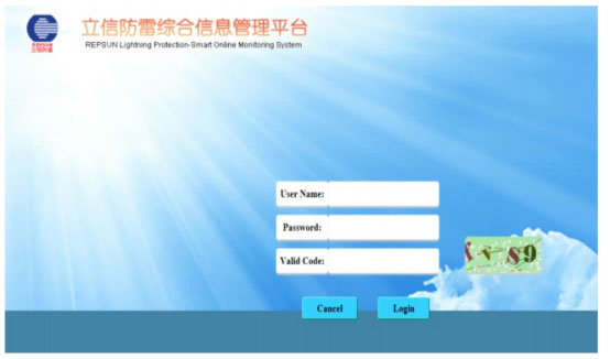
Действительный код должен быть написан строчными буквами.
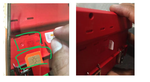
1.Как вставить SIM-карту в хост Smart GSM?
Прежде всего,мы видим схему рядом с портом SIM-карты,согласно схеме подсказка:поместите правильное направление карты,а затем вставить.
2.Как вытащить сим-карту из хоста Smart GSM?
Первый,нам нужно найти немного заостренные вещи (например,возвратная игла/перо,и т. д.),а затем используйте его, чтобы нажать на SIM-карту,и оно автоматически появится.
3. Как подключить резистор к хосту Smart GSM для проверки значения сопротивления?
Найдите подходящие резисторы перед тестированием.,Обратите внимание, что диапазон значений сопротивления нашего продукта составляет (0,01–500 Ом). Также убедитесь, что концы ПК и E хорошо подключены.
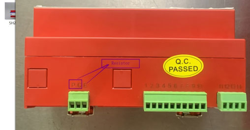
Почему нам нужно проверять его с помощью резистора, предназначенного для проверки точности нашей продукции.
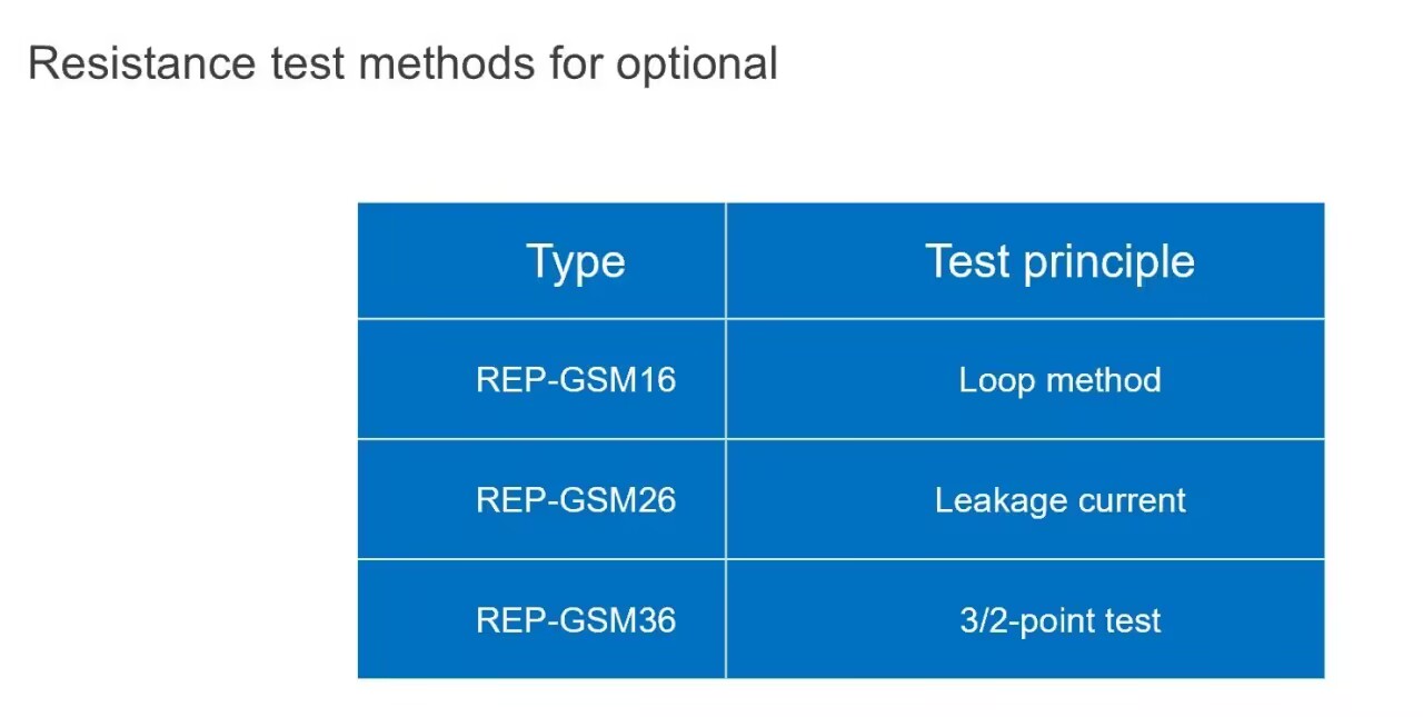
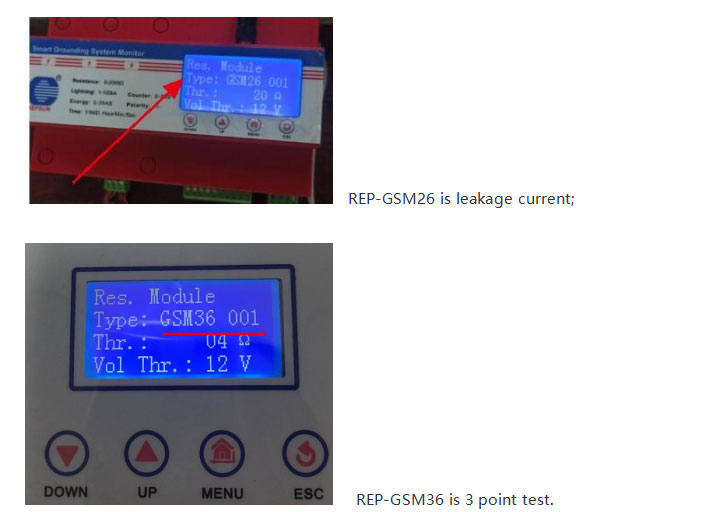
4. Сколько моделей Smart GSM имеет?
Три типа:
REP-GSM16 — это метод петли.;
REP-GSM26 — ток утечки;
REP-GSM36 — 3-точечный тест.
5.Как изменить модель хоста Smart GSM на"GSM36 001"?
①.Пожалуйста, измените его на"Тип:GSM36 001"затем нажмите кнопку MENU и кнопку ВВЕРХ, чтобы изменить его.
②.Тогда 001,также нужно нажать кнопку MENU, чтобы сохранить его
③."чр"также нужно нажать кнопку МЕНЮ
④."Том Четвёртый"также нужно нажать кнопку МЕНЮ
⑤.Наконец нажмите кнопку"ЭКУ"кнопка, если вы закончите предыдущий шаг,необходимо перезапустить Smart GSM, а затем еще раз проверить"Тип:GSM36 001"хорошо.
6.Как проверить значение сопротивления Smart GSM?
Умное GSM-тестирование:Перед тестированием Smart GSM необходимо убедиться, что состояние монитора сопротивления заземления включено.
Мы можем выполнить этот шаг, чтобы проверить это.:
①.Нажмите 1 раз кнопку МЕНЮ.,и найдите «Sys. Set.(System setup)», затем еще раз нажмите кнопку MENU.
②.Когда вы входите в «Sys. Установить (настройка системы)»,вам нужно найти"Res.Module (модуль сопротивления заземления)"нажмите еще раз кнопку МЕНЮ.
③.Когда вы входите в"Res.Module (модуль сопротивления заземления)",тебе нужно найти"Res.Monitor (монитор сопротивления заземления)"
④.Проверьте"Res.Monitor (монитор сопротивления заземления)"включен.
Убедитесь, что"Res.Monitor (монитор сопротивления заземления)"включен,тогда мы можем начать тестировать Smart GSM.
ПУТЬ 1:Веб-сайт, на котором можно нажать"Тест"затем ждем поступления данных.
ПУТЬ 2:Также можно нажать 4 раза кнопку ВНИЗ.,затем 1 раз для кнопки MENU. (Требуется непрерывное и последовательное нажатие.)
7.Как изменить информацию о версии веб-страницы?
Необходимо изменить: FMMon. (Удаленный мониторинг сигнала)
①.Нажмите кнопку"МЕНЮ"кнопка найти Sys. Установить. (Настройка системы), затем снова нажать кнопку"МЕНЮ"кнопка входа на новую страницу.
②.Найдите"FMMon. (Удаленный мониторинг сигнала), затем нажмите кнопку"МЕНЮ"кнопка входа на новую страницу.
③.Нажмите еще раз кнопку"МЕНЮ"кнопку и нажмите"ВВЕРХ"кнопка, чтобы изменить"НА"к"ВЫКЛЮЧЕННЫЙ"
④.Нажмите кнопку"МЕНЮ"кнопку, чтобы сохранить настройку.

УЗИП обеспечивает мониторинг окружающей среды и возможности связи (локально или удаленно) для определения состояния УЗИП, а также ожидаемого срока службы и, возможно, других функций, таких как интенсивность перенапряжения.,счетчик скачков напряжения,время всплеска,ток утечки,сопротивление заземления,подключение заземляющего провода,температура и влажность,и т. д.
Умный подразумевает две вещи:Взаимодействие с другими устройствами на основе удаленной связи (интернет вещей), и, возможно, запись анализа (чтобы сообщить пользователю, что SPD не удалось выполнить хороший,но почему это не удалось, разумнее).
Интеллектуальные УЗИП обычно включают в себя три функции.:Защита от перегрузки,мониторинг и связь.
Функция мониторинга состояния работы УЗИП&усилитель;определение параметров;может соответствовать интерфейсу связи&усилитель;удаленная передача данных.
В связи с тем, что большинство наших УЗИП имеют пластиковый корпус и детали.,в случае короткого замыкания или перегрузки УЗИП,будет рассеиваться большое количество тепла,пластиковый корпус или детали могут деформироваться,это может помешать спусковому механизму работать в соответствии с оригинальной конструкцией SPD.,и не отключается от основного питания. Поэтому из соображений двойной безопасности,Кроме того, на входе силового УЗИП мы также установили предохранитель или автоматический выключатель.
Но REPSUN SPD не требует предохранителя или автоматического выключателя, поскольку в REPSUN SPD уже есть резервный предохранитель для двойной безопасности.