Все системы заземления (SEA) обеспечивают эквивалентную защиту жизни и имущества. Однако каждая из них имеет определенные преимущества и неудобства в других терминах, которые могут быть важны для данной установки.
Как в коммерческих, так и в промышленных применениях потребности меняются, и становится все более важным выбрать правильную схему заземления системы в соответствии со строго определенными рабочими нормами, чтобы обеспечить совместное существование «высоких и низких токов» и удовлетворить требования оператора.
После анализа рисков, связанных с неисправностями изоляции установки, влияющими на безопасность людей и оборудования, в настоящем Техническом руководстве описываются три типа заземления системы, определенные стандартами IEC 60364 и NF C 15.100.
Каждая система заземления проверяется на безопасность и готовность, а также на защиту от перенапряжений и электромагнитных помех.
Терминология
В этой главе определены риски поражения электрическим током и электротравмы для различных систем заземления, как определено Международным электротехническим комитетом в стандарте МЭК 60364.
Системное заземление в LV характеризует заземление вторичной обмотки трансформатора HV/LV и заземление открытых проводящих частей установки. Таким образом, идентификация типов системного заземления определяется двумя буквами:
-
первая буква для подключения нейтрали трансформатора (2 варианта):
T — «заземленный»; I — «незаземленный» (или «изолированный»)
-
вторая буква для типа соединения открытых токопроводящих частей установки (2 варианта):
T — «непосредственно» заземленный; N — «подключенный к заземленной нейтрали» в начале установки.
Комбинация этих двух букв дает три возможные конфигурации:
Нейтраль трансформатора Открытые токопроводящие части
если Т Т или Н
если я Т
т.е. TT, TN и IT.
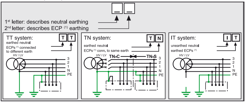
(1) ECP: открытая токопроводящая часть.
Примечание 1:
Система TN, согласно IEC 60364 и стандарту NF C 15-100, имеет несколько
подсистемы:
-
TN-C: если нейтральный провод N и проводник PE объединены (PEN)
-
TN-S: если нейтраль N и проводники PE разделены
-
TN-CS: использование TN-S после TN-C (обратное запрещено).
Обратите внимание, что TN-S является обязательным для систем с проводниками сечением y 10 мм2 Cu.
Примечание 2:
Каждое системное заземление может быть применено ко всей низковольтной электроустановке. Однако в одной и той же установке могут совместно существовать несколько схем.
Пример упрощенного расчета тока утечки на землю (Id)
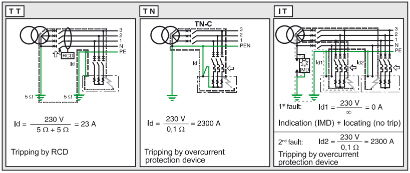
TT In the presence of an insulation fault, the fault current Id is limited for the most part by the earthing resistances (if the earthing connections for the exposed conductive parts and for the neutral are not combined).
This fault current induces a fault voltage in the load earthing resistances.
Since the earthing resistances are normally low and of the same order of magnitude (@10 W), this voltage of around Uo/2 is dangerous.
The part of the installation concerned by the fault must therefore be automatically disconnected by an RCD.
TNIn the presence of an insulation fault, the fault current Id is only limited by the impedance of the fault loop cables.
For 230/400 V systems, this voltage of the order of Uo/2 (if RPE = Rph) is dangerous as it is greater than the limit safety voltage, even in dry environments (UL = 50 V). The installation or part of the installation must then be immediately and automatically de-energised by an RCD.
As the insulation fault is similar to a phase-to�neutral short-circuit, breaking is performed by the overcurrent protection devices.
ITBehaviour on the 1st fault
-
Since the neutral is unearthed, there is no flow of a fault current Id. Voltage is not dangerous, and the installation can therefore be kept in operation
-
As the IMD (Insulation Monitoring Device) has detected this 1st fault, it must be located and eliminated before a 2nd fault occurs.
Behaviour on the 2nd fault
-
The fault concerns the same live conductor: nothing happens and operation can continue
-
The fault concerns two different live conductors.
The double fault is a short-circuit (as in TN). Breaking is performed by the overcurrent protection devices.
Function
TT This system sustains the "earth fault" ... but limits the consequences by implementing residual current devices which detect the earth fault before it becomes a short-circuit. This is the principle of the TT "directly earthed neutral" systems which allow the addition of extra outgoers by simply combining them with an RCD.
It is the safety champion!
-
In this case, as for short-circuits, the only contribution that can be made to availability is to enhance discrimination by installing several stages of earth leakage protection in order to reduce breaking to the smallest part of the system.
-
Note that RCDs are:
v built into or added to the circuit breaker and switch with the 0.5 to more than 100 A Multi 9 range
Ø built into the circuit breaker with the 100 to 630 A Vigi module
Ø built into the circuit breaker with the insulation monitoring module
Ø with separate toroid with the 100 to 6300 A
Vigirex devices which indicate absence of auxiliary supply source without causing tripping (avoids resets), and also warn the user of the insulation drop without causing tripping, by means of an early warning contact which is activated at half of the displayed threshold.
For example: set at 300 mA, it warns the user at 150 mA.
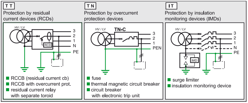
TN When a fault occurs, this system causes tripping of the SCPD (short-circuit protective device) to provide protection.This fault is similar to a short-circuit (very low fault loop impedance) and is thus violent and destructive.The circuit breaker therefore trips on the 1st fault.
-
This is the principle of the TN systems with exposed conductive parts connected to the neutral earthing point and which do not require additional protection devices such as RCDs or IMDs.It is thus the installation economy champion! This principle quickly becomes costly in the event of modifications or extensions, and is hard on installations due to short-circuit effects on cables and loads, as well as voltage drops which can disturb computers, MN undervoltage releases, motors, …
-
In order to limit the consequences of the fault to the part of the system concerned, current, time and energy discrimination methods must be implemented.
-
When the fault loop impedance is poorly controlled, it may be necessary to add additional protection of the residual current type. The NEC (National Electrical Code) requires earth-fault protection of TN-S systems by GFP (ground fault protection) devices or low-sensitivity RCDs. Moreover, the use of medium-sensitivity RCDs (300 mA) can also reduce the risk of fire by eliminating stray currents.
-
An extensive choice of 1P/3P/4P circuit breakers provides a perfect solution from 1 to more than 6300 A with the following ranges:
Ø Multi 9
Ø Compact
Ø Masterpact.
IT This system renders the fault inoffensive. It consists of attacking the cause rather than the effect by limiting the fault current to a few mA.
In an IT unearthed neutral or impedant neutral system, as the fault is not dangerous, there is no need to trip and operation can continue.
It is the electrical power availability champion!
-
However, leaving an earth fault on such a system would mean leaving a direct link between the system and the earth, as before. In this case, the appearance of a 2nd fault creates a dangerous current which must cause tripping of the same kind as in the TT and TN system earthing arrangements.
-
For this reason, this type of unearthed neutral system is only advantageous if real insulation faults are detected as soon as they appear by the Vigilohm System range which automatically and immediately detects faults on outgoers, including transient faults (which users particularly dread).
 Русский
 English
 Español
 العربية
 Français