WhatsApp:+86 15989059026 E-mail:info@xierli.com
Abstract: Manufacturers of SPDs understand that their devices will
eventually reach an end-of-life state, whether due to natural aging or due to
conditions being imposed which are outside of normal operating conditions.
International standards bodies such as the Electro Technical Commission (IEC) and Underwriters Laboratories Incorporated (UL) recognized the hazard posed by a failed SPD and include a number of tests in standards such as IEC 61643-12, IEC 62305-4 and UL 1449, to ensure that such devices fail in a safe manner. In order to comply with such standards, SPD manufacturers rely on “disconnectors”. This paper introduces the importance of SPD “disconnectors” to the safe installation of an SPD and expands on aspects such as,internal versus external disconnectors and over-current versus thermal disconnectors. It also details the current methods used to evaluate the behaviour of disconnectors by these various standards setting bodies and the steps being taken to improve on these in new draft editions under development.
An SPD by
definition contains at least one nonlinear component which is intended to limit
the surge voltage and divert the surge current. Inherent in the operation of
such devices is the possibility of unexpected failure or rapid end
of-life. Under such conditions, it is important that the SPD can safely isolate
itself from the prospective supply to which it is connected without presenting
a potential fire hazard.For this purpose a disconnector is usually
incorporated,either in the housing of the SPD itself (internal disconnector),
or as a separate component installed in the electrical network up-stream of the
SPD (external disconnector).
The
importance of such disconnectors to the safe operation of an SPD can not
be over emphasized. It is for this reason that manufacturers put so much
engineering effort into the careful design of disconnectors and standards
committees,such as UL 1449 and IEC 61643-1 , into the testing and
evaluation of such devices.
A well
designed SPD, or SPD installation, will generally require one or more
disconnectors for safe isolation from the prospective current of the energizing
supply during fault conditions. Without such, it is a potential fire hazard or
explosion waiting to happen.
The
failure mechanism of an SPD can generally be categorised as:
§ A gradual end-of-life due to natural degradation (ageing) of the internal non-linear component(s) during normal operation, or
§ A rapid
end-of-life due to a catastrophic event outside the scope of the SPD’s normal
range of operation.
These two
scenarios, by which an SPD can reach its end-of life, generally place very
different requirements on the disconnector(s).
Thermal
disconnector - In the first case, where the failure is associated with a
gradual degradation of the internal non linear components (metal oxide
varistors), a disconnector which is capable of sensing the thermal rise in
temperature of the SPD is generally required. The objective being to isolate
the failing varistor before it reaches thermal runaway and becomes a fire
hazard.
Gradual
degradation of the SPD can result from many causes, but most common amongst
these are:
§ Ageing
of the metal oxide varistor (MOV).
§ Sustained
temporary overvoltages (TOV) of the power system, either due to poor system
regulation (as in the case of long transmission lines), or when a
multiphase system becomes unbalanced (as in the case of a loose neutral
connection on US 120/240V systems).
Under such conditions, the rms current conducted by the SPD is usually limited to a few tens of amperes as it starts to enter conduction on the peaks of the sinusoidal supply, resulting in a progressive and gradual rise in temperature.
Over-current disconnector - In the case of the very rapid end-of-life (which can occur when an SPD is exposed to unanticipated events such as - a surge beyond its intended rating, or a large TOV as can occur when there is comingling of the HV and LV system) the disconnector must operate extremely fast in order to limit the energy of the prospective short-circuit current available from the supply to which it is connected. Under such conditions, a thermal disconnector would operate too slowly and the energy created in the failed SPD could result in a catastrophic explosion of the housing, and fire due to mains follow-current.
To prevent this, an “over-current disconnector” such as a fast acting fuse or magnetic circuit breaker with well coordinated I2t characteristic, is required. This need to include fast operating over-current disconnectors, has also meant that manufacturers need to grapple with a trade-off between fast isolation (high SCCR rating) and a low Imax (low maximum discharge current).
DC current disconnector – The growing interest in renewable energy generation has lead to a proliferation of photovoltaic panels in applications ranging from small residential installations to large commercial “sun farms”.Such installations by their very nature are externally located and thus particularly subject to the effects of lightning induced damage. As a result, the use of SPDs on such panels is becoming increasing important and new standards are being developed to address the testing and performance of SPDs intended for use on DC power systems. The disconnector in a DC-SPD needs to be designed in a very different way to that used in an AC-SPD. Not only does it often have to isolate much higher voltages (photovoltaic systems typically operate at 300, 600, 1000 VDC), but it also has to disconnect (open) when there is no zero crossing point to extinguish an arc as there would be on an AC system.
SPD
manufacturers are only just starting to address these more onerous
requirements. A number of innovative new disconnection designs have been developed
and patented.
Most of
these use various mechanical shutters to extend the arc length while
disconnecting, thereby cause self extinguishing even though a voltage
zero-crossing point is not present.
Surge Protection for Energy Storage Systems(ESS)
Energy Storage Systems (ESS) are now a mature technology. ESS is installed at sites to improve energy management control such as peak management or frequency regulation, or for renewable energy storage for photovoltaic or wind generated energy applications. The importance of such equipment makes interruption of their service unacceptable, so measures must be taken to limit damage due to external influences. One of the risks to be taken into account is possible damage due to transient overvoltages generated by lightning or by switching operations.
The deployment of ESS has demonstrated the limited robustness of these equipments, including batteries systems. Specialists in this technology have ascertained that their low impulse voltage withstand (Uw) may lead to critical system failure.
Surge Protector for ESS
Surge Protection Device (SPD) technology is widely used in AC power networks to protect equipment connected to them against transient overvoltages. Test standards (IEC61643-11), and selection and installation guides (IEC61643-12, IEC60364-5-534) have been in existance for many years, they define reliable products as well as their selection and implementation. However, regarding DC power networks, neither standardization is available at the time of writing (late 2020). In fact, the standards for surge protection for DC power are ongoing at international level (IEC) such as the following standards:
This standard IEC61643-31 is extrapolated from existing standards of surge protection devices for AC networks (IEC61643-11) and the sizing parameters (In, Uc, Imax, Up…) and test procedures is similar because they will be grouped in a new document common to the two documents.
The IEC 61643 series is moving toward a new philosophy. A new document (IEC61643-01) will gather all the definitions and tests common to the various applications of SPDs (AC power, PV power, Dataline, DC power) and the dedicated standards ( IEC61643-11, IEC6163-21, IEC61643-31, and coming IEC61643-41) will focus only on the specific tests for the application.
Regarding safety tests that simulate the end of life of the SPD such as thermal runaway or short circuit behavior, the procedures are therefore similar as well as the necessary means to achieve requirements, namely the use of internal disconnectors to withstand the thermal runaway tests, and associated fuses to withstand short-circuit tests.
The need to protect ESS equipement against transient over-voltages
Specialists in ESS equipment have noted a reduced robustness in impulse overvoltage of these equipments – particularly in battery systems – and due to the imperative need for continuity of service they recommend the use of surge protectors at their terminals. Surge protection on the AC part is also recommended. For the following reasons and consequences, the critical point is the protection of the battery storage system. When the maximum DC operating voltage is very high (1000 Vdc and more), in such cases a specific SPD is necessary, it being compatible with these voltages and in conformity with the future IEC61643-41. In cases of potentially extremely high short circuit current (100kA and more), the surge protector must withstand the short-circuit test being associated with a fuse sized accordingly.
To manage the short-circuit test, it is imperative that the surge protector is used with an external fuse. The fuse must be rated high enough to conduct 5kA at 8/20μs impulse current without opening, but rated low enough to protect the surge protector during its failure on the short-circuit test. Regarding the breaking capacity, this is the likely short circuit current calculated at the time of installation. Provided by the surge protection manufacturer, these requirements can make fuse rating selection somewhat difficult in the case of very high power DC installations.
Use of the existing upstream fuse
It could be considered to use the existing AC power SPD overload protection fuse upstream as protection of the SPD. This is only possible if its rating is equal to or less than the value declared by the manufacturer of the SPD. For high power installations, the fuses have very high ratings, making this option a non-starter.
ESS surge protector selection
In conclusion, the key criteria for the selection of DC SPDs, extrapolated from AC standards is:
* Type 2 Surge Protector (no proven risk of direct lightning discharge)
* Uc (max. operating voltage) is greater than Umax of the DC network + 10%
* In (Nominal discharge current) is greater than 5kA
* Isccr (admissible short-circuit current) with associated fuse is greater than Icc at the installation point.
(source: pewholesaler.co.uk by Switchtec Ltd)
To mitigate the effects of transient overvoltages, Surge Protective Devices (SPDs) are used throughout electrical distribution systems, such as at service entrances, transfer switches, and downstream panelboards. Manufacturers state surge capacity ratings as either Per Mode or Per Phase. This paper describes how these terms apply to SPDs used in three-phase, four-wire Wye systems.
SPD Modes Defined
In the context of SPDs, the term mode refers to the types of pathways available for shunting overvoltages. These pathways are most commonly formed by bridging two conductors through a Metal Oxide Varistor (MOV). These components are non-conductive at nominal circuit voltages, but become conductive when higher voltages are present. When that occurs, the varistor shunts excess voltage from the conductor of higher potential to the conductor of lower potential.
In a three-phase four-wire systems, four pathways are possible:
• Line-to-Neutral
• Line-to-Ground
• Neutral-to-Ground
• Line-to-Line
Each is shown in Figure 1.
Many three-phase applications use SPDs that offer complete line-to-neutral, line-to-ground, and neutral-to ground pathways, for a total of seven modes of protection. This arrangement is shown in Figure 2. SPDs that also provide line-to-line pathways offer 10 modes of protection. This brief will use seven-mode SPDs in subsequent examples.
Per Mode Rating Defined
An SPD’s per mode rating is based on the total amount of energy it can shunt from one circuit conductor to another. If an MOV capable of shunting a 50 kA of current is used in each pathway, then the per mode rating of the SPD in Figure 3 is 50kA.
If multiple MOVs are used between the same conductors, then the per mode rating will be the sum of the capacity of the MOV’s used in these pathways. Figure 4 shows a seven-mode SPD with three 50 kA MOVs installed between each pair of conductors. The per mode rating of this MOV is 150kA.
Per Phase Rating Defined
A different way to rate an SPD is to state the total capacity of the protective components serving each of the three phase conductors. Using the same seven-mode SPD with 50 kA MOVs, Phases A, B, and C are each served by two MOVs (one to neutral, one to ground). The per phase rating for the same SPD is 100 kA, as shown in Figure 5 below. Applying the same rating scheme to the SPD in Figure 4 above produces a per phase rating of 300 kA because each phase conductor is served by six 50 kA MOVs.
1.1:La technologie du paratonnerre REPSUN:
La dernière technologie basée sur les premières émissions de streamers.
1.2:La technologie du paratonnerre conventionnel:
Conception vieille d'environ 260 ans basée sur la technologie Franklin.
2.1:Principe de fonctionnement du paratonnerre REPSUN
UN. Le dispositif d'ionisation est chargé via les électrodes inférieures en utilisant le champ électrique ambiant (plusieurs millions de volts/mètre en cas d'orages).. Cela signifie que le système de paratonnerre REPSUN ESE est un système entièrement autonome ne nécessitant aucune alimentation externe.
B. Le phénomène d'ionisation est contrôlé par un dispositif qui détecte l'apparition d'un leader descendant,le champ électrique local augmente rapidement lorsqu'une décharge est imminente. Le paratonnerre REPSUN ESE détecte les charges sur le terrain,ce qui en fait la première aérogare ESE à réagir au moment précis où le leader descendant se développe du nuage au sol.
C. Déclenchement précoce du leader ascendant grâce à un système d'ionisation par étincelle entre les électrodes supérieures et la pointe centrale. La capacité du paratonnerre REPSUN ESE est de déclencher un leader ascendant avant tout autre point saillant dans la zone protégée, ce qui garantit qu'il sera le point d'impact préférentiel de la décharge de foudre.
2.2 Principe de fonctionnement d'une tige conventionnelle.
Cela dépend de la couronne naturelle et donc l'énorme courant circule à travers les tiges et les conducteurs de descente, ce qui entraîne des éclairs internes et une augmentation du potentiel de terre (c'est-à-dire. la tige attendra toujours que l'éclair tombe sur le bout de la tige). Dans le cas où les usines produisent naturellement des charges telles que des produits chimiques et des métaux qui peuvent attirer le courant de foudre sur ses parties métalliques. En ce moment,la partie métallique qui émet des charges devient plus active que le paratonnerre qui est inactif&li;le courant de foudre frappera la partie métallique plutôt que le paratonnerre.
3.1 Rayon de protection du paratonnerre REPSUN ESE VS paratonnerre conventionnel
Paratonnerre REPSUN ESE:Rayon de protection plus large selon la norme NFC17-102:2011
3.2 Paratonnerre conventionnel:Limiter le rayon de protection

REPSUN propose un nom d'utilisateur et des mots de passe pour se connecter au site Web de surveillance en ligne intelligent REPSUN comme ci-dessous:
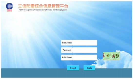
Le code valide doit être entièrement en minuscules.
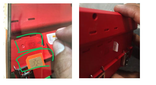
1.Comment insérer la carte SIM dans l'hôte Smart GSM?
Tout d'abord,on peut voir le schéma à côté du port de la carte SIM,selon l'invite du diagramme:mettre la bonne direction de la carte,puis insérez-le.
2.Comment retirer la carte SIM de l'hôte Smart GSM?
D'abord,il faut trouver des choses un peu pointues (par exemple,retour aiguille / plume,etc.),puis utilisez-le pour appuyer sur la carte SIM,et il apparaîtra automatiquement.
3.Comment connecter la résistance à l'hôte Smart GSM pour tester la valeur de résistance?
Trouver des résistances appropriées avant de tester,notez que la plage de valeurs de résistance de notre produit est de (0,01 à 500 Ω). Assurez-vous également que les extrémités PC et E sont bien connectées.
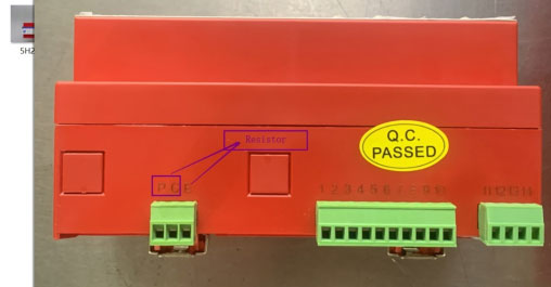
La raison pour laquelle nous devons le tester avec une résistance est conçue pour vérifier l'exactitude de nos produits.
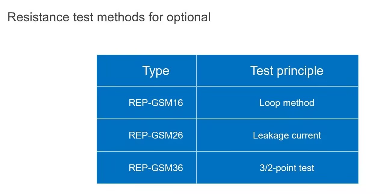
4.Combien de modèles de Smart GSM ont?
Trois types:
REP-GSM16 est une méthode en boucle;
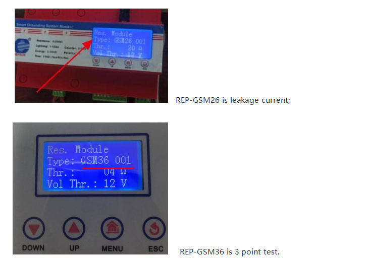
REP-GSM26 est un courant de fuite;
REP-GSM36 est un test en 3 points.
5.Comment modifier le modèle sur l'hôte Smart GSM pour"GSM36 001"?
①.Veuillez le changer en"Taper:GSM36 001"puis appuyez sur le bouton MENU et le bouton HAUT pour le modifier
②.Puis 001,il faut également appuyer sur le bouton MENU pour l'enregistrer
③."Thr"il faut également appuyer sur le bouton MENU
④."Vol Thr"il faut également appuyer sur le bouton MENU
⑤.Enfin, appuyez sur le bouton"ÉCHAP"bouton si vous avez terminé l'étape ci-dessus,devez redémarrer le Smart GSM puis vérifier à nouveau le"Taper:GSM36 001"est correct.
6.Comment tester la valeur de résistance du Smart GSM?
Test GSM intelligent:Avant le test Smart GSM, vous devez vous assurer que l'état du moniteur de résistance à la terre est activé.
Nous pouvons suivre cette étape pour le vérifier:
①.Appuyez 1 fois sur le bouton MENU,et trouvez le "Sys. Set. (Configuration du système) », puis appuyez à nouveau sur le bouton MENU.
②.Lorsque vous entrez dans le menu « Sys. Régler. (Configuration du système) »,tu dois trouver le"Res.Module (module de résistance de mise à la terre)"appuyez à nouveau sur le bouton MENU.
③.Lorsque vous entrez dans le"Res.Module (module de résistance de mise à la terre)",tu dois trouver"Res.Monitor (Moniteur de résistance à la terre)"
④.Vérifiez le"Res.Monitor (Moniteur de résistance à la terre)"est sur.
Assurez-vous que le"Res.Monitor (Moniteur de résistance à la terre)"est sur,nous pourrons alors commencer à tester le Smart GSM.
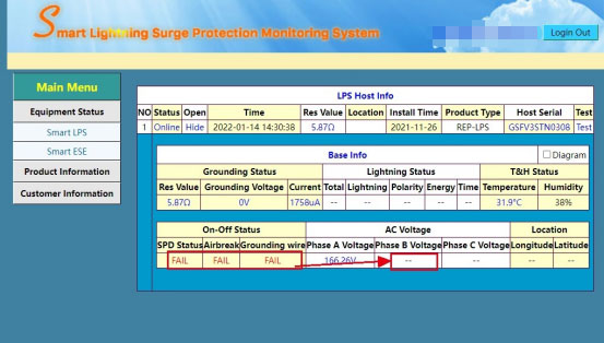
VOIE 1:Site Web pour cliquer sur le"Test"puis j'attends que les données arrivent.
VOIE 2:Vous pouvez également appuyer 4 fois sur le bouton BAS,puis 1 fois pour le bouton MENU. (Nécessite une pression continue et constante.)
7.Comment modifier les informations sur la version de la page Web?
Besoin de modifier : FMMon. (surveillance du signal à distance)
①.Appuyez sur la touche"MENU"bouton trouver le système. Set. (Configuration du système), puis appuyez à nouveau sur la touche"MENU"bouton entrer dans une nouvelle page.
②.Trouvez le"FMMon. (surveillance du signal à distance), puis appuyez sur le bouton"MENU"bouton entrer dans une nouvelle page.
③.Appuyez à nouveau sur le"MENU"bouton et appuyez sur"EN HAUT"bouton pour modifier le"SUR"à"DÉSACTIVÉ"
④.Appuyez sur la touche"MENU"bouton pour enregistrer le paramètre.

Un SPD assurant la surveillance de son environnement et sa capacité de communication (localement ou à distance) pour fournir l'état du SPD ainsi que l'espérance de vie et éventuellement d'autres fonctions telles que l'intensité des surtensions.,compteur de surtension,temps de surtension,Courant de fuite,résistance à la terre,connectivité du fil de terre,température et humidité,etc.
Intelligent implique deux choses:Interaction avec d'autres appareils basée sur une communication à distance (Internet des objets), et quand éventuellement une bande d'analyse (pour informer un utilisateur que SPD a échoué dans Nice,mais la raison pour laquelle il a échoué est plus intelligente).
Les SPD intelligents comprennent généralement trois fonctions:Protection contre les surtensions,suivi et communication.
Fonction de surveillance de l'état de fonctionnement du SPD&li;paramètres de détection;peut correspondre à l'interface de communication&li;transmission de données à distance.
Étant donné que la plupart de nos SPD ont un boîtier et des pièces en plastique,en cas de SPD court-circuité ou surchargé,une grande quantité de chaleur sera dissipée,le boîtier ou les pièces en plastique pourraient se déformer,cela pourrait empêcher le mécanisme de déclenchement de fonctionner comme la conception originale du SPD,et ne parvient pas à se déconnecter de l'alimentation principale. Donc pour une double raison de sécurité,De plus, au niveau du SPD de puissance en amont, nous avons également installé un fusible ou un disjoncteur.
Mais REPSUN SPD ne nécessite pas de fusible ni de CB car il y a déjà un fusible de secours dans REPSUN SPD pour une double sécurité.